Time Domain Vs Frequency Domain Reflectometers in Aviation Operations
Distance To Fault (DTF) measurements of coaxial cables and testing of antennas are typically performed by independent analyzers. Historically, aviation technicians have used Time Domain Reflectometers (TDR) to perform DTF measurements. A TDR sends a pulse of Direct Current (DC) of half sine wave into the coax cable copper pair and digitizes the return response of the reflected pulse in time domain. The difference in velocity of propagation (Vp) estimates the potential location of the problem. TDRs are limited as no information regarding the performance problems at actual operating radio frequency (RF) is determined.
What does an FDR do?

Image Source: https://www.anritsu.com/en-us/test-measurement/solutions/en-us/distance-to-fault
Frequency Domain Reflectometers performs a sweep of frequencies of the transmission line input, and then using Inverse Fast Fourier Transform (IFFT) on the reflected signals, convert them back to time domain. The analyzer not only performs the calculations of the DTF from the Vp received, but in addition receives all the reflected signals from the faults in the frequency spectrum that provides characteristics of the type of fault found. Therefore, users could create a characterization of the type of damage, i.e.: corrosion or bad shielding etc. It is also important when doing FDR test to consider the characteristics of the cable to compensate for any losses during the transmission.
An FDR could create characterizations of the type of fault found, not capable when using a TDR.
TDRs are not capable of troubleshooting antennas. Typically, operators will have to bring a more sophisticated equipment, such as a spectrum analyzer, if available, or swap antennas, as best way to discard possible problems with navigation systems. This process is time consuming, and costly to the operators, in particular if the no fault is found (NFF) with the antenna.
What technology is available approved for aviation?

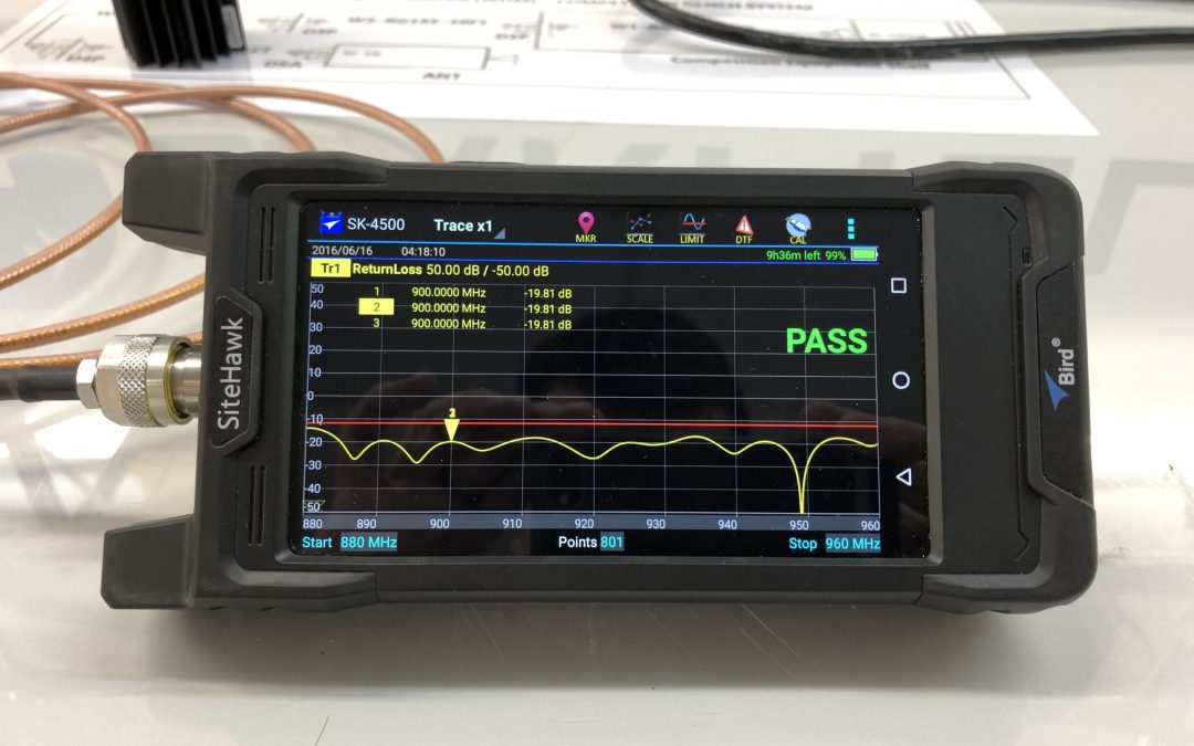
The FDR analyzer such as FlightHawk P/N 7003A001-4, is capable of performing both tasks in one analyzer: DTF and antenna frequency sweep. The FlightHawk sweeps in a frequency range of 1MHz to 6GHz, capable of connecting to any navigation system such as VHF, DME, TCAS etc. It contains a friendly user interface for the testing of coaxial cables and antennas with measurements in feet or meters for DTF and dB or Voltage Standing Wave Ratios (VSWR) for frequency sweeps. It is capable of integrating a power sensor to measure power output from the source.
The FDR analyzer such as FlightHawk P/N 7003A001-4, is capable of performing both tasks in one analyzer.
Finally, it uses an android base operating system that provides flexibility to store images of any measurement, downloadable via USB drive, Bluetooth or WIFI. This is particularly useful when line maintenance technicians require additional support from avionics techs or engineers remotely located.
Barfield contribution to this equipment to make it suitable for aviation, was identifying and including the library of commonly used coaxial cable part numbers with their characteristics. The versatility of the equipment and the ease of use, are part of the reasons that have been included in the Boeing Aircraft Maintenance Manual (AMM).
TDR could provide DTF measurements, but FDRs such as the FlightHawk is a more comprehensive, fast troubleshooting tool for line maintenance, helping avoid no fault founds.
Other articles:
- How the Boeing Frequency Domain Reflectometer Works?
- How Airlines Are Testing Aircraft to Bring Them Back to Service?
- How to use a Frequency Domain Reflectometer in Aviation?
Barfield Inc., in partnership with Bird continue supportting operators to help diagnose avionics problems.
If you still have more questions or want to learn more about this technology, please fill out the form below.
")


Recent Comments