Among the required instruments and equipment that all powered aircraft must-have is a Magnetic Direction Indicator.
The Magnetic Direction Indicator (Compass) is required to be installed so that its accuracy is not excessively affected by the aircraft’s vibration or magnetic fields and a placard must be installed on or near the compass which lists the calibration readings in not more than 30° increments for small aircraft or 45° for large aircraft.
FAA Advisory Circular AC No. 43-215, details five acceptable methods for compensating a standby compass or preparing the compass correction card. The 5 acceptable methods are:
- Compass Rose
Requires the use of a properly surveyed, constructed, calibrated, and certified for use compass calibration pad (compass rose).
- Master Sight Compass
Uses a calibrated and certified Master Sight Compass that is indexed 180° from normal which allows the user to stand facing the aircraft. No compass rose is required.
- Simulated Rotation
Uses an apparatus that is able to neutralize the Earth’s magnetic field around the aircraft and creates a simulated magnetic field which can then be rotated so that the aircraft may remain stationary. No compass rose is required.
- Portable Magnetic
Uses an apparatus composed of a highly accurate digital compass and a remote indicator for viewing with the standby compass. No compass rose is required.
- Air Swing
Is accomplished with the aircraft in flight using an electrically calibrated and compensated system or an Inertial Navigation System or an Attitude and Heading Reference System or a Global Positioning System.
When must a compass swing be accomplished?
Per the FAA (AC 43.13-1B CHG 1) page 620, paragraph 12-37.
A compass swing must be performed on the following occasions:
- When the accuracy of the compass is suspected.
- After any cockpit modification or major replacement involving ferrous metal.
- Whenever a compass has been subjected to a shock; for example, after a hard landing or turbulence.
- After the aircraft has passed through a severe electrical storm.
- After a lighting strike.
- Whenever a change is made to the electrical system.
- Whenever a change of cargo is likely to affect the compass.
- When an aircraft operation is changed to a different geographic location with a major change in magnetic deviation. (e.g., from Miami, Florida to Fairbanks, Alaska.)
- After the aircraft has been parked on one heading for over a year.
- When flux valves are replaced.
Barfield Sight Compass – SC063
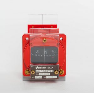
The Barfield SC063 (P/N 101-01200) is a portable, self-contained Master Sight Compass used to check the mounted aircraft compass. Consisting of a modified aircraft compass which has been re-screened to indicate 180 degrees from normal.
The SC063 allows the operator to stand facing the aircraft, making it considerably easier to transmit signals to and from the aircraft cockpit.
The SC063 is unique in that the compensating magnets have been removed and a combination magnifying lens and collimating sight added.
With the compensator removed the compass indicates magnetic direction at all times and is not subject to calibration offsets. The magnifying lens increases the readability of the dial and the collimating lens ensures precise sighting alignment.
Attached to the rear of the compass is an adjustable sight lens. The lens is precisely aligned to ensure that the overall accuracy of the dial does not exceed ±1 degree. The Sight Compass is painted orange and has a caution label attached to it to prevent inadvertent installation in an aircraft.
How to use the SC063 Sight Compass?
PRE-SWING INSTRUCTIONS
- When using the Compass, the operator stands directly in front of the aircraft at a minimum distance of 30 feet, preferably 50 feet or more.
- The Compass is held as nearly level as possible and sighted through the sighting lens to the exact center of the aircraft.
- Sufficient time should be allowed for the Sight Compass to stabilize before taking readings. It is best to take a series of three readings before assuming that the readings are correct.
- Normal procedure is to either taxi or tow the aircraft to approximately the desired heading as read on the Compass to be compensated (within 5 degrees).
- The operator using the Sight Compass, then standing directly in front of the aircraft and with the Sight properly lined on the centerline of the aircraft, observes the exact heading on which the aircraft is positioned, and notes any error that exists between the Sight Compass and the Aircraft Compass being compensated.
- Whatever error exists between the Sight Compass and the Aircraft heading is then corrected by moving the Aircraft the number of degrees difference existing until such time as the Aircraft heading and the reading of the Sight Compass are corrected for the desired heading (within 5 degrees).

COMPASS COMPENSATION PROCEDURE
Note: All these corrections shall be made using a non-magnetic screwdriver. The Compass shall be lightly tapped after each adjustment and be allowed time to settle before taking readings.
- Set the compensator for zero effect by matching the dots on the compensator screws with the fixed dots on the case.
- Align the Aircraft as nearly as possible (not to exceed 5 degrees error) to magnetic north (0°).
- Turn the N-S screw to cause the Aircraft Compass to read the same as the Sight Compass.
- Align the Aircraft as nearly as possible (not to exceed 5 degrees error) to magnetic east (90°).
- Turn the E-W screw to cause the Aircraft Compass to read the same as the Sight Compass.
- Align the aircraft as nearly as possible (not to exceed 5 degrees error) to magnetic south (180°).
- Turn the N-S screw to remove one-half of the error between the Aircraft Compass and the Sight Compass.
- Align the Aircraft as nearly as possible (not to exceed 5 degrees error) to magnetic west (270°).
- Turn the E-W screw to remove one-half of the error between the Aircraft Compass and the Sight Compass.
CAUTION: IF THE N-S SCREW IS INADVERTENTLY TURNED, THE NORTH HEADING MUST BE RECHECKED AND COMPENSATED
COMPASS SWINGING PROCEDURE
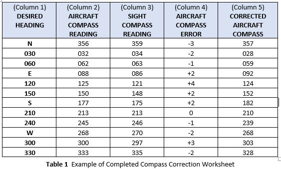
- Prepare a worksheet similar to the one shown in Table 1 with Column 1 filled in and the Column Titles entered for the other columns. The worksheet will be populated with the data recorded and calculated by accomplishing the steps that follow.
- Starting on any convenient 30 degree heading, align the Aircraft so that the Sight Compass reads within 5 degrees of the desired heading.
- Record the Aircraft Compass reading in column 2 and the Sight Compass reading in column 3 adjacent to the appropriate heading in column 1.
- Repeat steps B and C for each subsequent 30 degree heading.
- Record the difference between the readings of the Aircraft and Sight Compass readings in column four (4).
- Add or subtract the Compass errors in column 4, to or from, respectively, the desired headings in column 1. Enter the results in column 5.
- There should not be more than plus or minus 10° difference between any of the Aircraft Compass readings and the Sight Compass readings. If the Aircraft Compass cannot be adjusted to meet the requirements, install another one.
- Enter the values from column 5 in the “STEER” portion of the Aircraft Compass correction card.

Do you need the instruction manual? Click here


Recent Comments