Ground Support Test Equipment, MRO Services
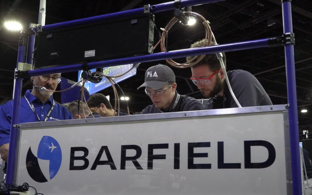
DPS1000 Barfield[/caption]The Aerospace Maintenance Competition is back in 2023, and this time Barfield will be participating with the following benches.
Find below information to prepare you for the competition.
Air Data Testing

For Air Data Testing participants will be working with a DPS1000. The The DPS1000 is Barfield’s latest fully automated, user-friendlyRVSM compliant air data test set. The DPS1000 performs altimeter and static systems tests and inspections. Critical components used in the DPS1000 have a well established history of proven flight line accuracy including pumps, valves and static/altitude transducers.
Check the DPS1000 procedure here
Intermittent Fault Detector
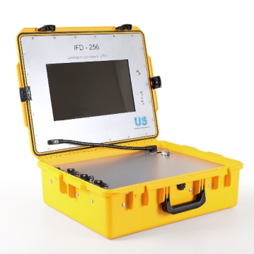
Avionics technicians often are faced with the uncertainty when troubleshooting to decide where the root of the problem is loicated in complex wire harnesses.
Barfield in partnership with Universal Synaptics, the industry leader in detecting and isolating elusive intermittent faults, will have a bench to troubleshoot with IFD-512.
These are some articles and training videos that help understand the use of this tool:
Ground Support Test Equipment, MRO Services
REVISED VERSION
The Aerospace Maintenance Competition is back, and this time Barfield will be participating with 3 test benches.
Find below information to prepare you for the competition.
Air Data Testing
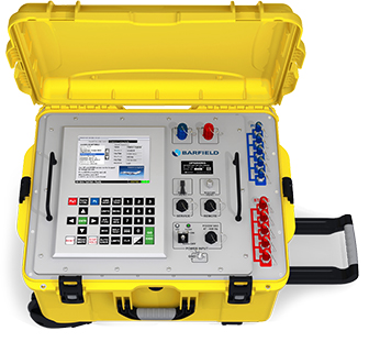
For Air Data Testing participants will be working with a DPS500NG. The DPS500NG is Barfield’s latest fully automated, intuitive RVSM compliant air data test set. The DPS500NG is a portable, high precision, dual channel air data pressure test system. This tester is designed to calibrate, test and troubleshoot air data instrumentation and aircraft pitot-static systems. The test set has been designed with functional and reliability features highly suited to withstand the harsh environmental and demanding conditions of the flight line environment. The test set is designed for testing a wide range of commercial and military aircraft, both rotary and fixed wing. Designed with both hardware and software safety features, the DPS500NG provides maximum protection for the test set and the Unit Under Test (UUT). These features include over-range, overlimit, and over-pressurization protection, micro-porous filters, pressure relief valves, UUT isolation in the event of a power failure and more
Check the DPS500NG procedure here
Bonding
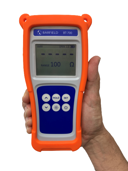
Proper electrical bonding and grounding is critical for aviation operations. This year Barfield released its latest product the BT-700 and BT-700i (intrinsically safe). The Barfield Bond Meter Series are designed with the clearest and most informative displays for mistake-free usage. They quickly produce accurate readings to reduce the time spent measuring. The unique low-power techniques avoid the hassle of power cords or battery chargers. The BT-700/BT-700i will run for 100 hours on 3 standard AA batteries and has auto power-off to preserve them. Probes are often more important than the instrument. This year participants will have the opportunity to work with a Kelvin Clip Probe and a Big Kelvin Display Probe.
The blog post How The Next Generation of Bond Meters Are Helping Aviation Technicians? incorporates videos of how to use the bond meter. The Barfield Bond Meter Quick Start Guide is also a very helpful tool to learn how to use it.
Check the BT700 procedure here (revised version)
RF Antenna Testing

Avionics technicians often are faced with the uncertainty when troubleshooting to decide if the problem is the avionics Line Replaceable Unit (LRU) or the coaxial connection from the LRU to the antenna.
The FlightHawk is a tool that helps avionics professionals mitigate the problem by testing the coaxial connection from the LRU to the antenna. It has two main functionalities:
- Distance to Fault
- Measuring the VSWR (Voltage Standing Wave Ratio) to determine the energy reflection form the antenna
- Some kits come with a power sensor and a terminal load, that allow for testing the power coming out of the LRU. Thus, converting the FlightHawk into a Power Meter
These are some articles and training videos that help understand the use of this tool:
Check the RF Antenna Testing Procedure here

Ground Support Test Equipment
No Fault Found (NFF) is a standard term used in aviation, and typically happens when a part removed from an aircraft, due to poor performance, is sent to an MRO repair shop for testing. The repair shop cannot replicate or find the problem. The MRO shop tests the unit and if it passes all tests, the unit is sent back to the operator as NFF.
Now, the same unit could continue having problems that cannot replicate on the bench. Many times, micro-breaks, bad soldering, vibrations, could create intermittences that are undetectable by standard equipment. The unit is removed and sent back to the MRO shop and the cycle continues. Airlines often-times have a policy to retire the unit after three NFF test results. This unit will be considered “rogue” or unserviceable.
Aircraft OEMs, also have processes to deal with rogue units.
At the MRO level, depending on the Component Maintenance Manual (CMM) for the particular part, Original Equipment Manufacturers (OEM) will provide a set of instructions on how to perform a deep test on the unit. This will entail doing a temperature test and a vibration test to capture the anomaly (“bake and shake”).
It is highly probable that after performing the deep test, with environmental stimulus (“baking and shaking”), the unit is returned to service and continues to present problems.
What are the different intermittence stages in No-
Fault Founds?
One of the possible reasons that vibration and temperature chambers still would not be able to replicate the problem is related to the sensitivity of the equipment. There are three stages in which intermittences occur.
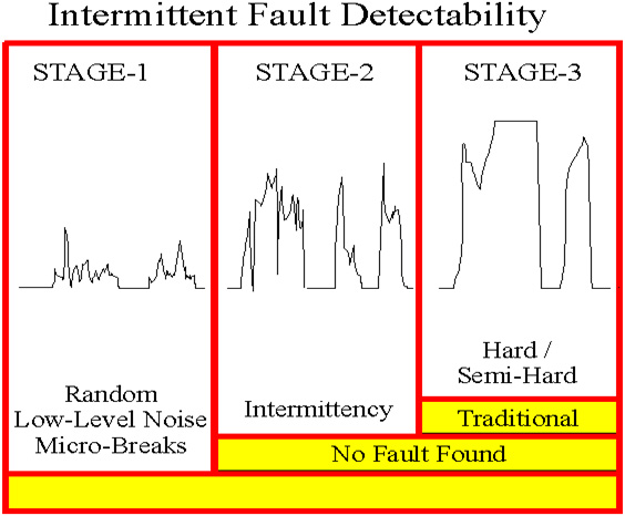
Stage 1 Stage 2 Stage 2 intermittences graph for NFFs
- Stage-3 hard or semi-hard failures can be captured by most test equipment on the bench or the line.
- Stage-2 faults that manifest intermittently in operation, but pass the deep test, and labeled NFF.
- Stage-1 random low-level nanosecond micro-breaks or noise, likely not operationally evident.
Equipment capturing Stage-3 hard or semi-hard fault is not built and not capable of capturing Stage-1 or Stage-2 intermittent faults where these micro-breaks are detected.
Micro-breaks could occur as follows:
• Cracked solder joint.
• Broken wire.
• Loose crimp connection.
• Loose or corroded wire wrap.
• Corroded connector contact.
• Sprung connector receptacle.
• Deteriorated wire insulation.
• Hairline crack in printed circuit trace.
• Unsoldered connection.
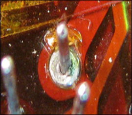 Micro-breaks due to corrosion. Source: Universal Synaptics |
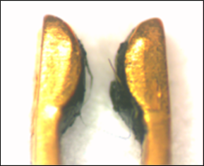 Micro-break due to bad contact. Source: Universal Synaptics |
(more…)

Ground Support Test Equipment
Turbine temperature indicating systems are critical for proper aircraft maintenance. This article helps explain the main difference between the Barfield TT1000A and TT1200A test sets.
What do they do?
The three primary functions of a Barfield turbine temperature test set are:
- Measure the Resistance of the aircraft thermocouple loop system.
- Measure the insulation between either of the thermocouple conductors and the airframe chassis.
- Test the cockpit indicator using a thermocouple simulator.
Additionally, the Barfield Turbine Temperature Test Sets also have the ability to:
- Simulate the in-line resistance required on many older indicating systems.
- Provide cold junction compensation (for ambient) at the point of connection.
- Measure the engine temperature directly, as it may be used as a master indicator.
Why do aircraft operators need these tools?
Their main purpose is to be able to Test, Troubleshoot and Certify the accuracy of the aircraft’s Turbine Temperature Indicating System.
This is accomplished by using the aircraft’s maintenance manual (AMM) to determine the specific tests required with their allowable tolerances and the Barfield supplied instruction manual which details the test set configuration and hook-up information for the test procedures.
How does the tool interact with the engine and the instruments of the aircraft?
The Barfield Turbine Temperature Test Sets are used to test the aircraft wiring, thermocouple sensors, and the cockpit indicator. Typically, this is done using a divide and conquer scheme where the aircraft wiring and thermocouple sensors are isolated from the cockpit indicator or indicating system and tested separately.
The equipment is then used to test and troubleshoot in order to find and repair or replace any components not meeting the required specifications for either resistance or insulation. The indicator is then tested apart from the aircraft wiring and thermocouple sensors using the tester’s thermocouple simulator to perform an indicator run-out to confirm accuracy and linearity.
What aircraft uses these tools?
The Barfield Turbine Temperature Test Sets may be used on any and all types of aircraft that have some form of a turbine engine(s) whether turbofan, turboprop, or turboshaft, and which use chromel-alumel (K type) thermocouples to sense the engine temperature.
Why are they important for aviation owners?
They are important to ensure that their aircraft engine temperature indicating systems are reading accurately.
Various issues with the aircraft indicating system will cause the cockpit indication to read lower than it should and so there is an increased risk of over-temping the engine if the system is not certified.
Thus, technicians rely on their test equipment to return aircraft back to service.
What are their differences?
| FEATURE |
TT1200A |
TT1000A |
| Display Temperature |
°C, °F & Millivoltage |
°C only |
| Thermocouple range |
Up to 1372° |
Up to 1000°C |
| Temperature display resolution |
0.1°C |
1°C |
| Backlit 16 Character |
Yes |
No |
| Does it require separate 45V battery (or Converter with 9V)? |
No |
Yes |
| Access to batteries without disassembly |
Yes |
No |
| Is the housing ruggedized and highly visible? |
Yes |
No |
| Number of resistance and insulation ranges |
4, 4 |
2, 1 |
| Resistance measurements to |
0.001Ω |
0.01Ω |
| Insulation measurements to |
200MΩ |
2MΩ |
| Smart Calibration alert reminder Technology |
Yes |
No |
| Timed measurement with Display Hold feature for Resistance and Insulation functions |
Yes |
No |
| Embedded password security to prevent unauthorized access to certain options of the menu |
Yes |
No |
| Standard and custom test leads are connected using same panel mounted cannon plug |
Yes |
No |
In summary:
Both the TT1200A and TT1000 Test Sets provide:
- 4-Wire Resistance Measurements to perform the required system resistance measurements
- 45V Insulation Test to test for insulation breakdown of the wiring, sensors, and interconnects
- A Thermocouple Simulator to perform Indicator run outs
- Temperature measurement and may be used as a master indicator
- Resistance simulation to provide the required in-line resistance for non-powered analog indicators
- Cold Junction Compensation at the clips for much faster temperature stabilization
Use the TT1200A if the aircraft engine temperature indicating system requires greater than 1000°C or has indications in °F or if the temperatures are presented with 0.1-degree resolution.
Also, use the TT1200A if the system or any individual components have resistance values specified to resolutions of 0.001Ω or have any insulation test requirements of greater than 2MΩ specified.
Otherwise, the TT1000A could meet the turbine temperature requirements.
Where to find the manuals?
To learn more about the proper usage and interfacing of the test sets, please refer to the appropriate Instruction Manuals, available on our website barfieldinc.com.
Contact us here, to get more information.

Ground Support Test Equipment
Every avionics technician understands the importance of proper grounding to prevent damages to the instruments, especially if hit by lightning.
Bond meters are a special tool used in aviation to measure low resistance. Their purpose is to measure proper bonding and aircraft grounds. Thus, minimizing damages of expensive and complex systems; increasing aviation safety.
Why not use a multimeter to measure grounds?
It seems ubiquitous to use a multimeter also to measure grounds, but the range of a standard multimeter may not meet many aviation requirements.
A standard multimeter can only measure resistance as low as 0.1Ω that is 100mΩ.
This is not enough!
Some aircraft manuals require 2.5 milliohms (2.5mΩ) for correct ground measurement. If using the standard multimeter, the measurement is 40 times higher than required by the manual!!!
What is The Difference Between a Bond Meter and a Multimeter?
The multimeter can measure resistance, capacitance, voltages, and current. When measuring low resistance, a standard multimeter is limited by the level of range and the introduction of additional resistance from the pair of leads. The additional resistance is caused by the 2-wire measurement method as shown below.
A 4-wire measurement, also called a 4-wire Kelvin testing, provides the proper ground measurement as follows:
Out of the four (4) wires, two (2) provide the current to the Device Under Test (DUT), and the other two (2) measure the voltage over the DUT.
This way, the measurement is taken exactly between the desired points. Thus, eliminating the added resistance from the standard pair of leads used in the multimeter.
What makes the BT-700 and BT-700i unique?
The BT-700 and BT-700i (intrinsically safe) offer some great features in comparison with legacy bond meters.
- Durable, versatile with intuitive user-interface.
- Battery life of 100 hours in standby, 50 hours in 10 mΩ range*
- Four and one-half (4½) digit LCD with LED Backlight
- Easy to clean
- Automatic and manual HOLD modes
- Programmable test limits with OK and FAIL annunciator
- OVER and UNDER annunciators
- Open lead and DUT (Device Under Test) detection
- Durable: Meets MIL-PRF-28800F, Class 2 requirements
- Optional Tilt Stand/Magnet/Hanger
*Factors such as range, backlight, and use of the optional display probe will affect battery life.
** Images sourced from cirris.com.
Display Probes With a Hold Mode?
This unique feature allows an aviation technician to read a measurement at the fingertips, with the option to hold the value and see have an annunciator button set to the right threshold.
Just imagine how fast measurements of grounds throughout the aircraft can be taken. Just set the threshold, and start measuring
If you are interested to learn more about it? Download the manual below
Fill this form to download it.

Ground Support Test Equipment
Among the required instruments and equipment that all powered aircraft must-have is a Magnetic Direction Indicator.
The Magnetic Direction Indicator (Compass) is required to be installed so that its accuracy is not excessively affected by the aircraft’s vibration or magnetic fields and a placard must be installed on or near the compass which lists the calibration readings in not more than 30° increments for small aircraft or 45° for large aircraft.
FAA Advisory Circular AC No. 43-215, details five acceptable methods for compensating a standby compass or preparing the compass correction card. The 5 acceptable methods are:
- Compass Rose
Requires the use of a properly surveyed, constructed, calibrated, and certified for use compass calibration pad (compass rose).
- Master Sight Compass
Uses a calibrated and certified Master Sight Compass that is indexed 180° from normal which allows the user to stand facing the aircraft. No compass rose is required.
- Simulated Rotation
Uses an apparatus that is able to neutralize the Earth’s magnetic field around the aircraft and creates a simulated magnetic field which can then be rotated so that the aircraft may remain stationary. No compass rose is required.
- Portable Magnetic
Uses an apparatus composed of a highly accurate digital compass and a remote indicator for viewing with the standby compass. No compass rose is required.
- Air Swing
Is accomplished with the aircraft in flight using an electrically calibrated and compensated system or an Inertial Navigation System or an Attitude and Heading Reference System or a Global Positioning System.
When must a compass swing be accomplished?
Per the FAA (AC 43.13-1B CHG 1) page 620, paragraph 12-37.
A compass swing must be performed on the following occasions:
- When the accuracy of the compass is suspected.
- After any cockpit modification or major replacement involving ferrous metal.
- Whenever a compass has been subjected to a shock; for example, after a hard landing or turbulence.
- After the aircraft has passed through a severe electrical storm.
- After a lighting strike.
- Whenever a change is made to the electrical system.
- Whenever a change of cargo is likely to affect the compass.
- When an aircraft operation is changed to a different geographic location with a major change in magnetic deviation. (e.g., from Miami, Florida to Fairbanks, Alaska.)
- After the aircraft has been parked on one heading for over a year.
- When flux valves are replaced.
Barfield Sight Compass – SC063
The Barfield SC063 (P/N 101-01200) is a portable, self-contained Master Sight Compass used to check the mounted aircraft compass. Consisting of a modified aircraft compass which has been re-screened to indicate 180 degrees from normal.
The SC063 allows the operator to stand facing the aircraft, making it considerably easier to transmit signals to and from the aircraft cockpit.
The SC063 is unique in that the compensating magnets have been removed and a combination magnifying lens and collimating sight added.
With the compensator removed the compass indicates magnetic direction at all times and is not subject to calibration offsets. The magnifying lens increases the readability of the dial and the collimating lens ensures precise sighting alignment.
Attached to the rear of the compass is an adjustable sight lens. The lens is precisely aligned to ensure that the overall accuracy of the dial does not exceed ±1 degree. The Sight Compass is painted orange and has a caution label attached to it to prevent inadvertent installation in an aircraft.
How to use the SC063 Sight Compass?
PRE-SWING INSTRUCTIONS
- When using the Compass, the operator stands directly in front of the aircraft at a minimum distance of 30 feet, preferably 50 feet or more.
- The Compass is held as nearly level as possible and sighted through the sighting lens to the exact center of the aircraft.
- Sufficient time should be allowed for the Sight Compass to stabilize before taking readings. It is best to take a series of three readings before assuming that the readings are correct.
- Normal procedure is to either taxi or tow the aircraft to approximately the desired heading as read on the Compass to be compensated (within 5 degrees).
- The operator using the Sight Compass, then standing directly in front of the aircraft and with the Sight properly lined on the centerline of the aircraft, observes the exact heading on which the aircraft is positioned, and notes any error that exists between the Sight Compass and the Aircraft Compass being compensated.
- Whatever error exists between the Sight Compass and the Aircraft heading is then corrected by moving the Aircraft the number of degrees difference existing until such time as the Aircraft heading and the reading of the Sight Compass are corrected for the desired heading (within 5 degrees).

COMPASS COMPENSATION PROCEDURE
Note: All these corrections shall be made using a non-magnetic screwdriver. The Compass shall be lightly tapped after each adjustment and be allowed time to settle before taking readings.
- Set the compensator for zero effect by matching the dots on the compensator screws with the fixed dots on the case.
- Align the Aircraft as nearly as possible (not to exceed 5 degrees error) to magnetic north (0°).
- Turn the N-S screw to cause the Aircraft Compass to read the same as the Sight Compass.
- Align the Aircraft as nearly as possible (not to exceed 5 degrees error) to magnetic east (90°).
- Turn the E-W screw to cause the Aircraft Compass to read the same as the Sight Compass.
- Align the aircraft as nearly as possible (not to exceed 5 degrees error) to magnetic south (180°).
- Turn the N-S screw to remove one-half of the error between the Aircraft Compass and the Sight Compass.
- Align the Aircraft as nearly as possible (not to exceed 5 degrees error) to magnetic west (270°).
- Turn the E-W screw to remove one-half of the error between the Aircraft Compass and the Sight Compass.
CAUTION: IF THE N-S SCREW IS INADVERTENTLY TURNED, THE NORTH HEADING MUST BE RECHECKED AND COMPENSATED
COMPASS SWINGING PROCEDURE
- Prepare a worksheet similar to the one shown in Table 1 with Column 1 filled in and the Column Titles entered for the other columns. The worksheet will be populated with the data recorded and calculated by accomplishing the steps that follow.
- Starting on any convenient 30 degree heading, align the Aircraft so that the Sight Compass reads within 5 degrees of the desired heading.
- Record the Aircraft Compass reading in column 2 and the Sight Compass reading in column 3 adjacent to the appropriate heading in column 1.
- Repeat steps B and C for each subsequent 30 degree heading.
- Record the difference between the readings of the Aircraft and Sight Compass readings in column four (4).
- Add or subtract the Compass errors in column 4, to or from, respectively, the desired headings in column 1. Enter the results in column 5.
- There should not be more than plus or minus 10° difference between any of the Aircraft Compass readings and the Sight Compass readings. If the Aircraft Compass cannot be adjusted to meet the requirements, install another one.
- Enter the values from column 5 in the “STEER” portion of the Aircraft Compass correction card.

Do you need the instruction manual? Click here
Contact us here, to get more information.


Recent Comments