How to use a Frequency Domain Reflectometer in Aviation?
Barfield Inc., in partnership with Bird, collaborated in the development of the FlightHawk ( formerly known as SiteHawk-AV). This is a Frequency Domain Reflectometer (FDR), commonly used in the telecommunication industry, modified to be used in aviation operations. It can usually be found under Part Number: 7003A001-5 in many manuals.
Training on how to use the FlightHawk:
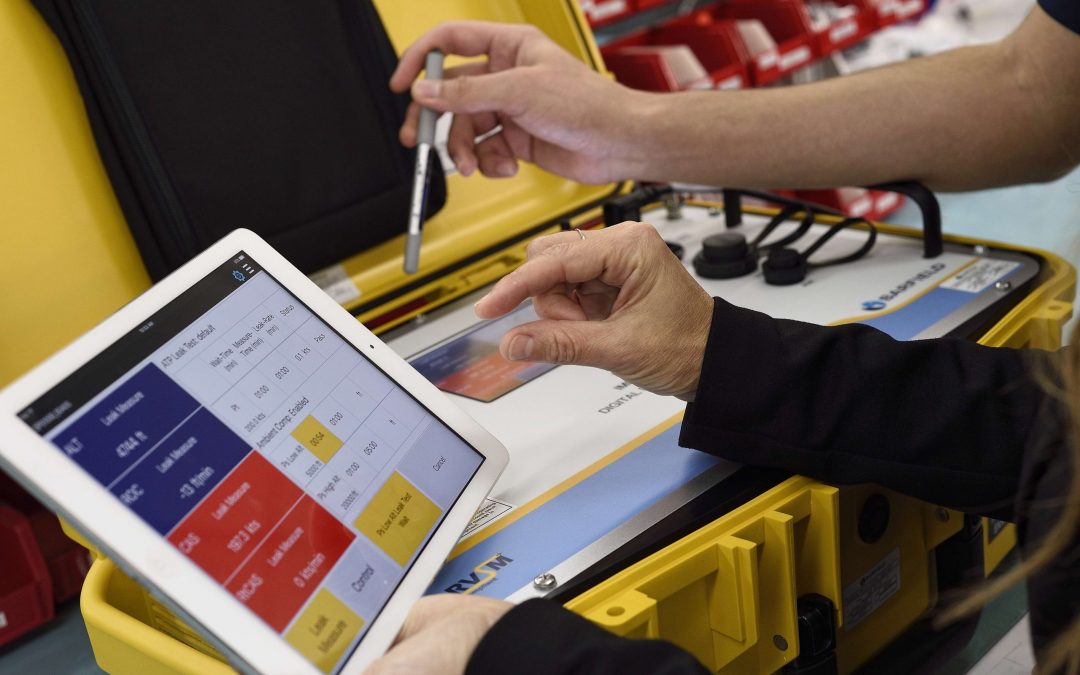
The FlightHawk is a Frequency Domain Reflectometer that connects from the end of the coaxial cable, testing if damages exist by identifying the Distance to Fault (DTF) and capable of performing a frequency sweep to the antenna.
The following videos provide instructions that allow the testing of any type of antenna and coaxial cables with this Frequency Domain Reflectometer, in any navigation systems of any aircraft.
- Introduction to FlightHawk ( formerly known SiteHawk-AV).
- Antenna and Cable Health Checks: Boeing Use case.
- How to Calibrate the FlightHawk.
- VSWR and return loss sweep with the FlightHawk.
- Distance to Fault Test Using FlightHawk.
- Sending files from the FlightHawk to an Android phone.
- Save files from FlightHawk to a USB Drive.
1. Introduction to the FlightHawk
This video is an introduction of the FlightHawk. It explains what it consists of and what features are included.
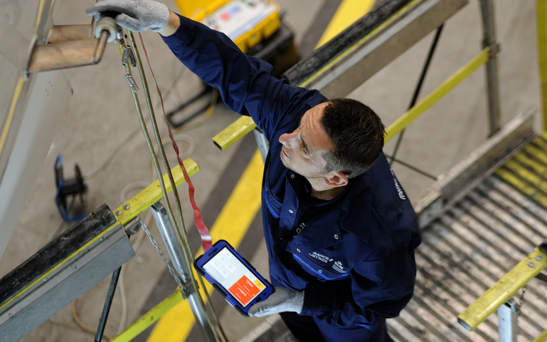
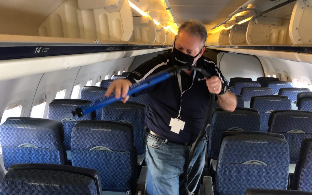
2. Antenna and cable health checks: Boeing use case
This video is a presentation from Boeing, showing details of the use of the FlightHawk in an aircraft.
3. How to calibrate the FlightHawk
This video shows the process of how to calibrate the Frequency Domain Reflectometer.
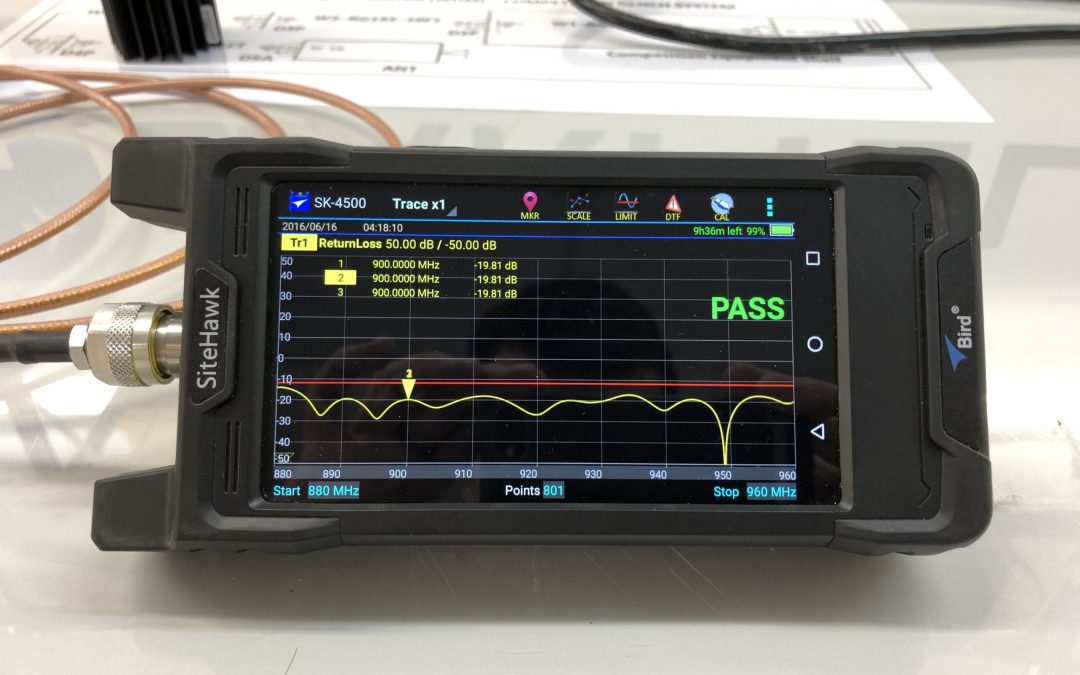
4. VSWR and return loss sweep with the FlightHawk
This video shows how to do a Voltages Standing Wave Ratio (VSWR) and return loss frequency sweep.
5. Distance to fault test using the FlightHawk
This video shows the Distance To Fault (DTF) test procedure.
6. Sending files from the FlightHawk to an Android phone
This video shows how to send files from the Frequency Domain Reflectometer to an Android phone. It is a great tool for saving images and results from tests performed.
7. Save files from FlightHawk to a USB drive
This video is about how to save files from the FlightHawk to a USB drive. It is also, a great tool for saving images and results from tests performed.
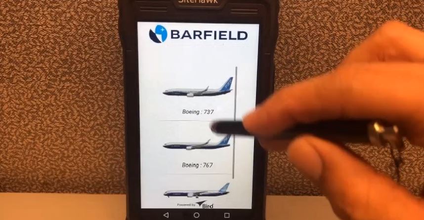
We hope with these videos, to give you an overall understanding of the FlightHawk Frequency Domain Reflectometer (FDR). The videos showed how to perform Distance to Fault (DTF) and VSWR testing. For Boeing operators, there is an additional option, a Boeing App, that can be installed on your device.
If you still have more questions or want to send us a quote, please fill out the form below.


Recent Comments