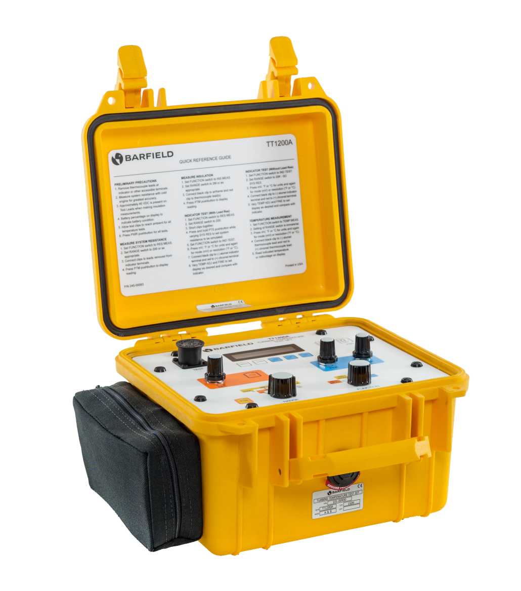
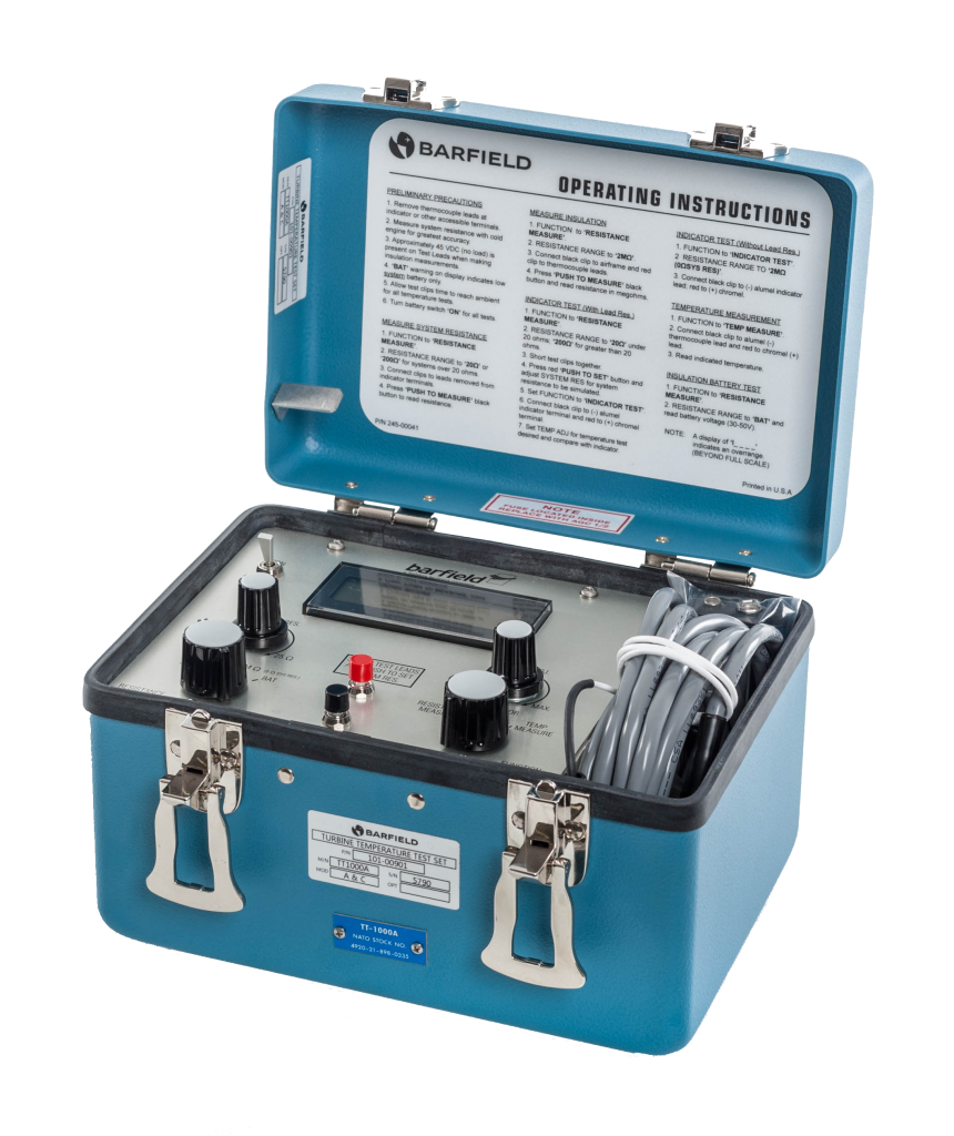
This is a brief description of some of the concerns regarding the proper point for interfacing the Barfield TT1000A and TT1200A test sets into the aircraft Turbine Temperature Indicating System.
Where to break into the aircraft engine temperature indicating system to perform Indicator tests?
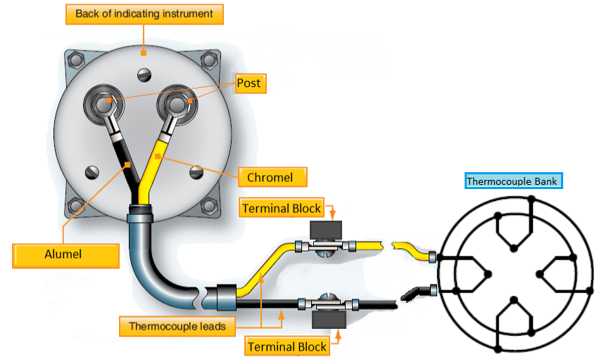
Break at the engine terminal block
If the aircraft indicator is a servo, digital, or glass, it is recommended breaking into the system at the engine terminal block.
Test at the indicator
Note that if the indicator does not use aircraft power and has only 2 posts for the electrical connections then it is NOT recommended to break into the terminal block.
This type of system is powered solely by the millivoltage from the thermocouples and must be tested at the indicator.
The indicator is calibrated to measure K type thermocouple millivoltage with a specific in-line resistance, typically 8.00 ohms.
If the Test Set is configured to simulate the 8.00 ohms and interfaced at the terminal block, then the indicator will see the simulated 8 ohms plus the combined resistance of the Chromel and Alumel wire lengths between the terminal block and the indicator.
The result will be that the indicator will read lower than the Test Set display.

Where to find the manuals?
To learn more about the proper usage and interfacing of the test sets, please refer to the appropriate Instruction Manuals, availble on our website barfieldinc.com: 56-101-00901 or 56-101-00930


Recent Comments