Why Are Turbine Temperature Testers Critical In Aviation?

Why Are Turbine Temperature Testers Critical In Aviation?

Turbine temperature indicating systems are critical for proper aircraft maintenance. This article helps explain the main difference between the Barfield TT1000A and TT1200A test sets. 

What do they do?   

The three primary functions of a Barfield turbine temperature test set are:

  1. Measure the Resistance of the aircraft thermocouple loop system.
  2. Measure the insulation between either of the thermocouple conductors and the airframe chassis.
  3. Test the cockpit indicator using a thermocouple simulator.

Additionally, the Barfield Turbine Temperature Test Sets also have the ability to:

  1. Simulate the in-line resistance required on many older indicating systems.
  2. Provide cold junction compensation (for ambient) at the point of connection.
  3. Measure the engine temperature directly, as it may be used as a master indicator.

Why do aircraft operators need these tools?

Their main purpose is to be able to Test, Troubleshoot and Certify the accuracy of the aircraft’s Turbine Temperature Indicating System.

This is accomplished by using the aircraft’s maintenance manual (AMM) to determine the specific tests required with their allowable tolerances and the Barfield supplied instruction manual which details the test set configuration and hook-up information for the test procedures.

How does the tool interact with the engine and the instruments of the aircraft?

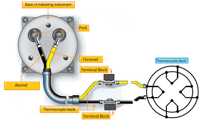
The Barfield Turbine Temperature Test Sets are used to test the aircraft wiring, thermocouple sensors, and the cockpit indicator.  Typically, this is done using a divide and conquer scheme where the aircraft wiring and thermocouple sensors are isolated from the cockpit indicator or indicating system and tested separately.

The equipment is then used to test and troubleshoot in order to find and repair or replace any components not meeting the required specifications for either resistance or insulation. The indicator is then tested apart from the aircraft wiring and thermocouple sensors using the tester’s thermocouple simulator to perform an indicator run-out to confirm accuracy and linearity.

What aircraft uses these tools?

The Barfield Turbine Temperature Test Sets may be used on any and all types of aircraft that have some form of a turbine engine(s) whether turbofan, turboprop, or turboshaft, and which use chromel-alumel (K type) thermocouples to sense the engine temperature.

Why are they important for aviation owners?

They are important to ensure that their aircraft engine temperature indicating systems are reading accurately. 

Various issues with the aircraft indicating system will cause the cockpit indication to read lower than it should and so there is an increased risk of over-temping the engine if the system is not certified.

Thus, technicians rely on their test equipment to return aircraft back to service.
TT1000 Schematic Barfield

What are their differences?


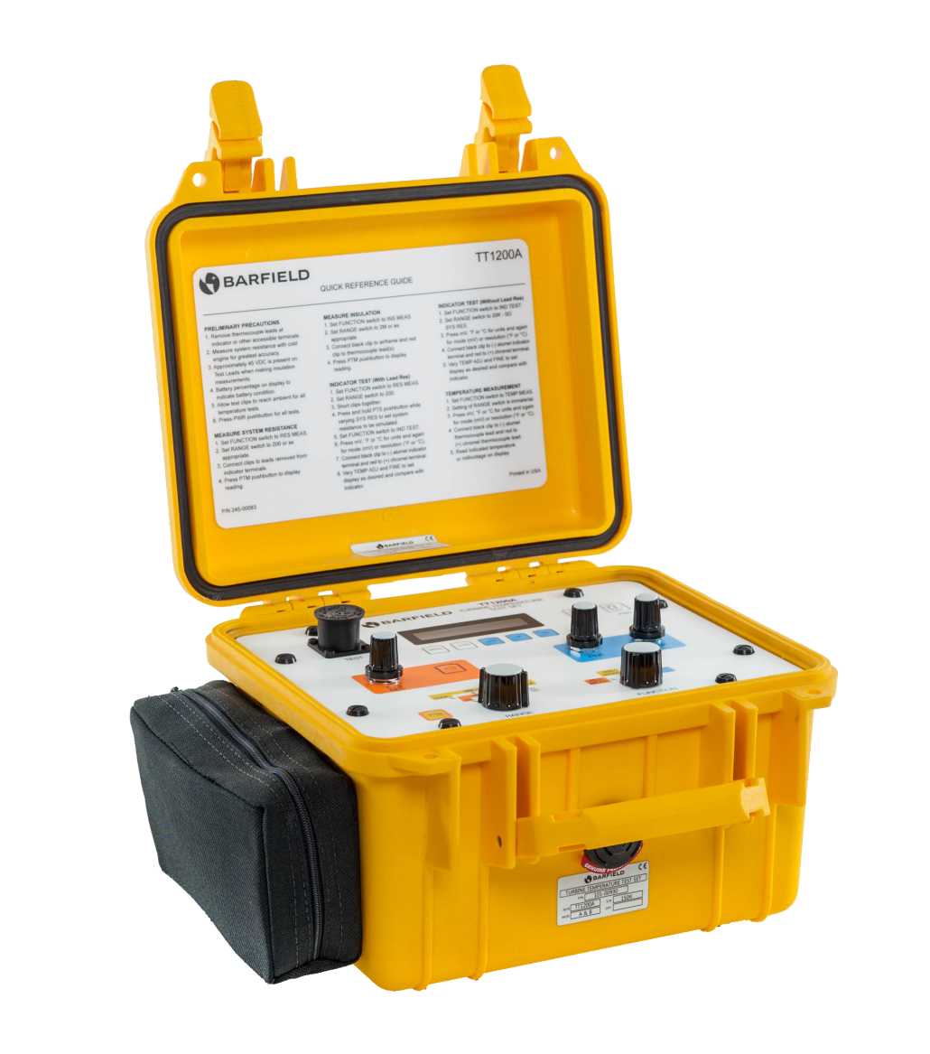
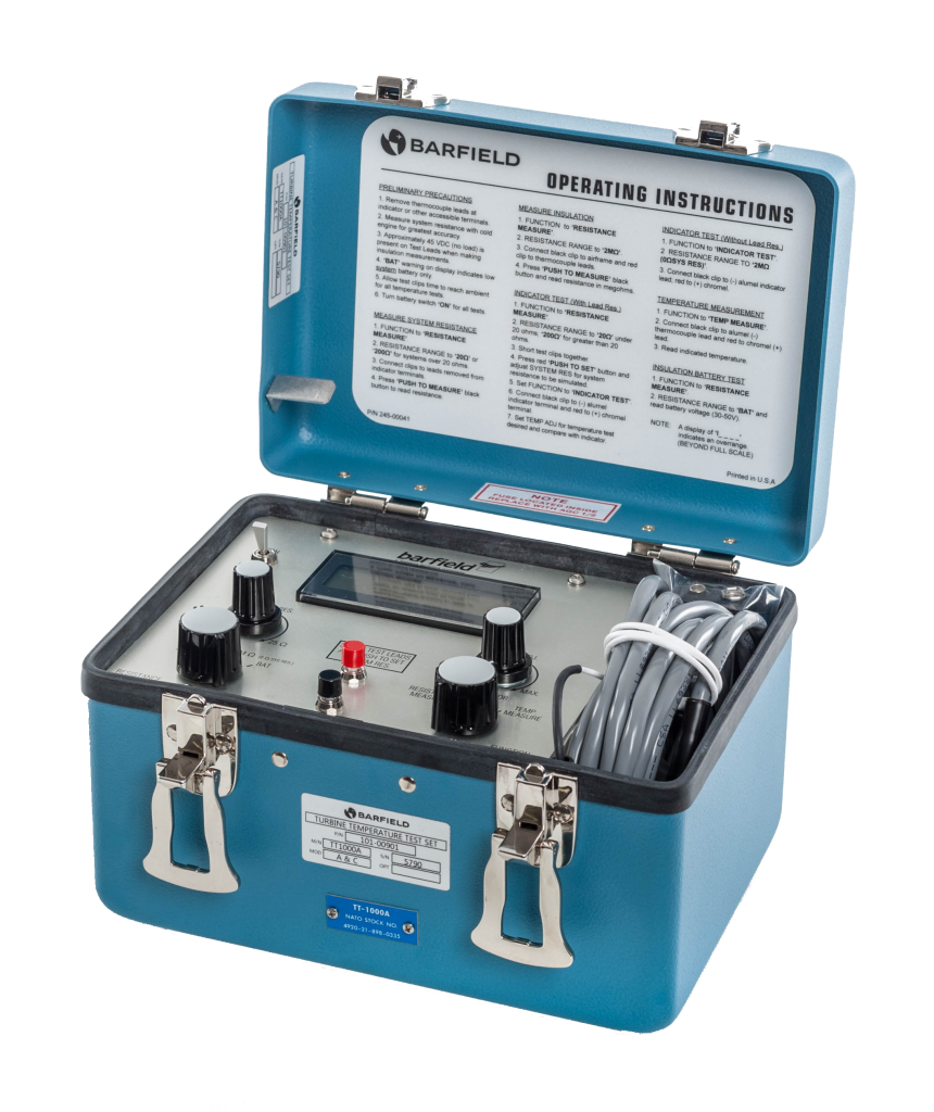
FEATURE TT1200A TT1000A
Display Temperature °C, °F & Millivoltage °C only
Thermocouple range Up to 1372° Up to 1000°C
Temperature display resolution 0.1°C 1°C
Backlit 16 Character Yes No
Does it require separate 45V battery (or Converter with 9V)? No Yes
Access to batteries without disassembly Yes No
Is the housing ruggedized and highly visible? Yes No
Number of resistance and insulation ranges 4, 4 2, 1
Resistance measurements to 0.001Ω 0.01Ω
Insulation measurements to 200MΩ 2MΩ
Smart Calibration alert reminder Technology Yes No
Timed measurement with Display Hold feature for Resistance and Insulation functions Yes No
Embedded password security to prevent unauthorized access to certain options of the menu Yes No
Standard and custom test leads are connected using same panel mounted cannon plug Yes No

In summary:

Both the TT1200A and TT1000 Test Sets provide:

  1. 4-Wire Resistance Measurements to perform the required system resistance measurements
  2. 45V Insulation Test to test for insulation breakdown of the wiring, sensors, and interconnects
  3. A Thermocouple Simulator to perform Indicator run outs
  4. Temperature measurement and may be used as a master indicator
  5. Resistance simulation to provide the required in-line resistance for non-powered analog indicators
  6. Cold Junction Compensation at the clips for much faster temperature stabilization

Use the TT1200A if the aircraft engine temperature indicating system requires greater than 1000°C or has indications in °F or if the temperatures are presented with 0.1-degree resolution.

Also,  use the TT1200A  if the system or any individual components have resistance values specified to resolutions of 0.001Ω or have any insulation test requirements of greater than 2MΩ specified.

Otherwise, the TT1000A could meet the turbine temperature requirements.

Where to find the manuals?

To learn more about the proper usage and interfacing of the test sets, please refer to the appropriate Instruction Manuals, available on our website barfieldinc.com.
TT1000 Temperature Tester - Barfield
TT100A
Frequently Asked Questions About Barfield GSTE Products

Frequently Asked Questions About Barfield GSTE Products

Having all your questions about Barfield products answered for a better experience, is one of our main objectives. Our customer support and engineering teams have compiled an extensive list of Frequently Asked Questions to save you time.  

Where can I find the Barfield App on my mobile device to use with my DPS1000 and/or 1811NG? 

Connect your mobile device to the Internet via local Wi-Fi network or phone provider data plan, visit the Apple App or Google Play, search and download the “Barfield ADTS” app.  

Here are the links: 

Apple App Store 

Google Play 

How do I connect my DPS1000 and 1811NG to a mobile device? 

Find the detailed process in this article published on our blog: How to connect the DPS1000 and 1811NG to a Tablet 

What is the password to connect Barfield ADTS app to the DPS1000 and 1811NG ? 

Refer to the link: How to connect the DPS1000 and 1811NG to a Tablet 

Does my mobile device Wi-Fi need to be connected to a local network to connect and work with my DPS1000 and/or 1811NG? 

No, the test set is equipped with Wi-Fi Direct which works pier-to-pier, it connects and communicates directly between the mobile device through the Barfield ADTS App to the DPS1000 or 1811NG.  

How can I get my latest software update on my DPS1000 and 1811NG? 

Through your mobile device: Having the Barfield ADTS App up to date on the mobile device will ensure that your test equipment runs with the latest software (HUIM and PCM) installed.  The App detects the equipment’s current firmware and triggers a message with the need to run the software update.  The customer can choose to run the update or do it later, but the App won’t run the Test Equipment until the sotfware is updated. 

Visiting Barfield’s website: Barfield GSTE website

How can I register my Barfield product? 

You can register any of your Barfield products including the products distributed by Barfield by clicking on the following link: Warranty Registration 

What is the warranty on my Barfield product?  

All warranties are 1 year 

Exception:  The  DPS1000 and 1811NG  have a 2 year warranty.  

What is the calibration interval of my Barfield product? 

All DPS1000 and 1811NG have a 1-year calibration cycle. 

Analog instruments may require calibration every 6 months. Refer to the specific Instruction Manual for more information.  

Where can I find the latest manuals and information letters? 

The information on the latest manuals and information letters can be found on the GSTE page here 

What is the difference between calibration vs bench check? 

An inspection/verification from a third-party, non-Barfield authorized repair station, is not considered recertification of the Test Equipment. It determines, at best, if the Test Equipment’s performance meets Barfield’s published specifications.  It is important to clarify that Recertification does NOT result in any adjustments to the measurement system. 

The process of Calibration requires the Unit Under Test (UUT) be compared to Certified Traceable Standards.  Adjustments are made to the UUT during calibration in order to align the UUT to the exact values of the Standards so that the errors at all required test points are zeroed out. 

A true Calibration results in the equipment operating at its optimum accuracy and performance levels, which ensures the instrument will maintain its performance specification for another year until the next annual calibration recertification is due.    

In summary, the recertification (calibration) is normally required to be performed every year; “inspection-verification” is NOT recertification. 

Where can I send my Barfield equipment for calibration and repair? 

Barfield Test Equipment can be sent to Barfield Headquarters. Please, contact our customer support at gste.service@barfieldinc.com   

For Barfield authorize repair station contact gsesales@barfieldinc.com 

If you have any more questions about Barfield products fill out the form below 


How to interface a TT1000A and TT1200A with an Aircraft?

How to interface a TT1000A and TT1200A with an Aircraft?

This is a brief description of some of the concerns regarding the proper point for interfacing the Barfield TT1000A and TT1200A test sets into the aircraft Turbine Temperature Indicating System. 

Where to break into the aircraft engine temperature indicating system to perform Indicator tests?   

Break at the engine terminal block

If the aircraft indicator is a servo, digital, or glass, it is recommended breaking into the system at the engine terminal block.

Test at the indicator

Note that if the indicator does not use aircraft power and has only 2 posts for the electrical connections then it is NOT recommended to break into the terminal block.

This type of system is powered solely by the millivoltage from the thermocouples and must be tested at the indicator.

The indicator is calibrated to measure K type thermocouple millivoltage with a specific in-line resistance, typically 8.00 ohms.

If the Test Set is configured to simulate the 8.00 ohms and interfaced at the terminal block, then the indicator will see the simulated 8 ohms plus the combined resistance of the Chromel and Alumel wire lengths between the terminal block and the indicator.

The result will be that the indicator will read lower than the Test Set display.

TT1000 Schematic Barfield

Where to find the manuals?

To learn more about the proper usage and interfacing of the test sets, please refer to the appropriate Instruction Manuals, availble on our website barfieldinc.com:  56-101-00901  or 56-101-00930  

TT1000 Temperature Tester - Barfield
TT100A