How to set the limits of the DPS1000 and 1811NG?

How to set the limits of the DPS1000 and 1811NG?

Using incorrect limits can cause damage to sensitive components and aircraft systems. 

For that reason, it is very important to ALWAYS verify and ensure the limits selected are appropriate for the aircraft and/or the instruments that are going to be tested. 

The DPS1000/1811NG Test Sets come with two (2) pre-defined sets of operating limits – the default limits profile and the max limits profile. These limits are available for each of the of the three (3) operating modes – AeronauticalPressure units and EPR. 

Both DPS1000 and 1811NG Test Sets include a setting that allows creating and saving custom limits. With this feature, the customer can easily access and use the custom limits again in the future.

The values for both limits profiles are stored in an R/O“read only”, file. The Test Set will first power up and initialize with the default limits profile. As a result, if the customer changes the limits to the max or custom limits profile, the Test Set will power up using the last profile selected.  

The Test Set limits must be configured with the appropriate values to protect the aircraft system or instrument(s) about to be tested. 

“…it is very important to ALWAYS verify and ensure the limits selected are appropriate for the aircraft and/or the instruments that are going to be tested.

How to set up the limits 


NOTE: Before creating new limits refer to the appropriate AMM (Aircraft Maintenance Manual) or CMM (Component Maintenance Manual) for the actual minimum and maximum values to be applied. 

 A. If the limits don’t exist:  

Go to Setup 2 and create the limit file following these steps: 

  1. From Main Menu display, press Page 2” button 
  2. Screen is displayed with four options (Setup 1, Setup 2, Setup 3 and Change User Pin#). Select Setup 2.  
  3. From keypad screen, input user PIN (manufacturing default PIN: 123456– unless already changed by the user).  
  4. Select Limits Create/Edit/Delete.  
  5. Select Create Custom Limits – enter the parameter values for ALT, ROC, CAS, RtCAS, MACH, and ALR (Auto Leak Recovery). Note: You can select each parameter by touching the parameter or cycle through each parameter using the “Enter” key.  

Note: It’s recommended to Save the Limits with the aircraft name. 

The limits profile currently in use is displayed on the right upper quadrant of the screen (Figure 1). 
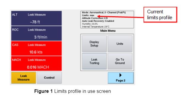
DPS1000 Front Screen Image

B. Selecting limits: 

If the operating limits exist because they were already created gto Setup 1 and select the limit file following these steps: 

  1. From Main Menu, press “Page 2” button 
  2. Screen is displayed with four options (Setup 1, Setup 2, Setup 3 and Change User Pin#)Select Setup 1. 
  3. Touch Limits View/Select key. 
  4. Touch “Select Limits” 
  5. Select applicable limit from the list displayed. 
  6. Click OK. 

NOTE: The tables showing the default and max limits profile values included in the DPS1000/1811NG Test Sets can be found in the corresponding user instruction manuals under “Appendix B: Operating Limits. 

Viewers of this article also were interested on How to Connect the DPS1000 and 1811NG to a Tablet 

Have you Registered your Barfield Product?

Registering your product validates your warranty and provides yout technical updates

Electrostatic Spraying in Aircraft Operations

Electrostatic Spraying in Aircraft Operations

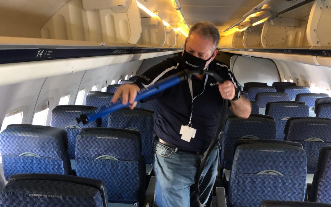
Barfield Inc., in partnership with George T. Baker Aviation Technical College, tested the Electrostatic Sprayer Cart inside an aircraft.

Electrostatic sprayers are making in-roads into aviation operations as a way to disinfect, by using its wrap around technologies.

Electrostatic sprayer works with a combination of an air pump and an electrostatic charge. Thus, charging the disinfectant particles positively. Once sprayed the adhere to negative charged surfaces. Check the link How Electrostatic Sprayer Works? to learn more about the technology.

“We found that doing a row could take about 5 seconds, and covering a 737 could be around 10 to 15 minutes on average.”

What type of Electrostatic Sprayers Exist?

In the market, there are two types of sprayers each one with a different type of connectivity. Low power battery operated and Industrial Electrostatic Sprayers powered with AC current. The low power units have a small motor that pushes the air out. It creates more like a mist. This could work for small spaces.

The Industrial Electrostatic Sprayers, like the Electrostatic Sprayer Cart, uses a powerful air pump which allows for a wider spread of the disinfectant.

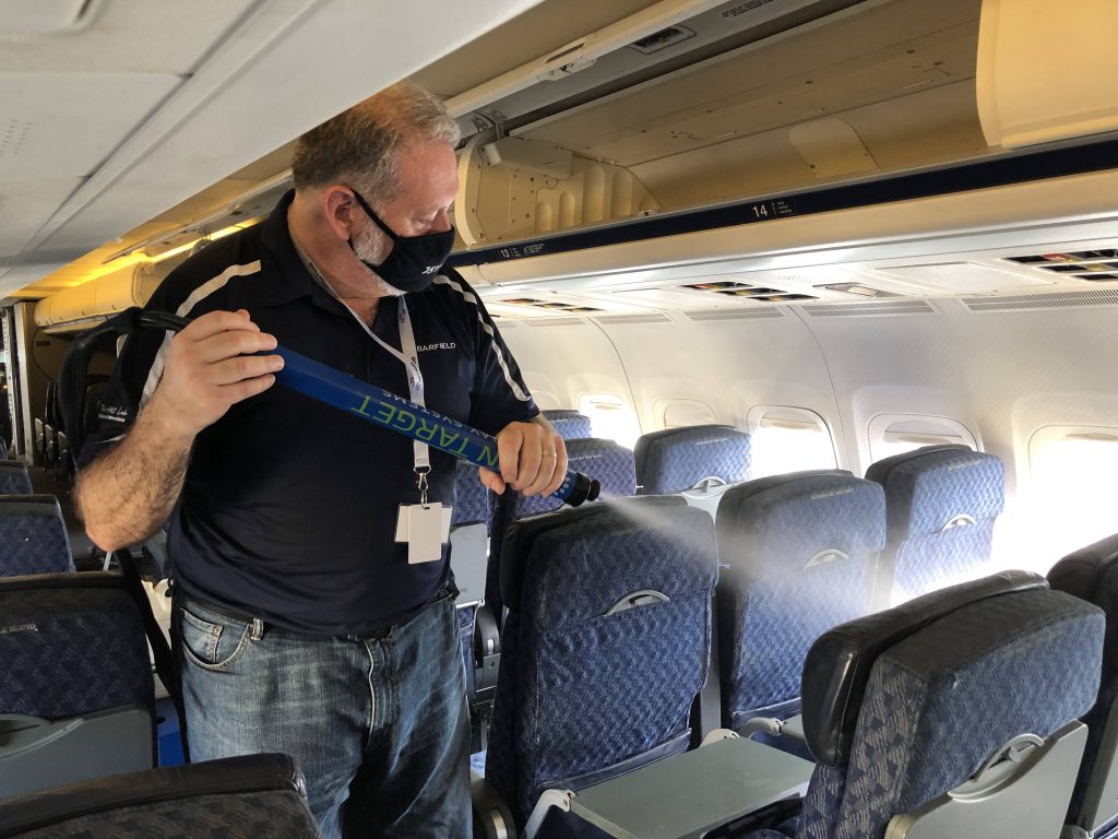
Electrostatic Sprayer On Target Barfield Inside Aircraft
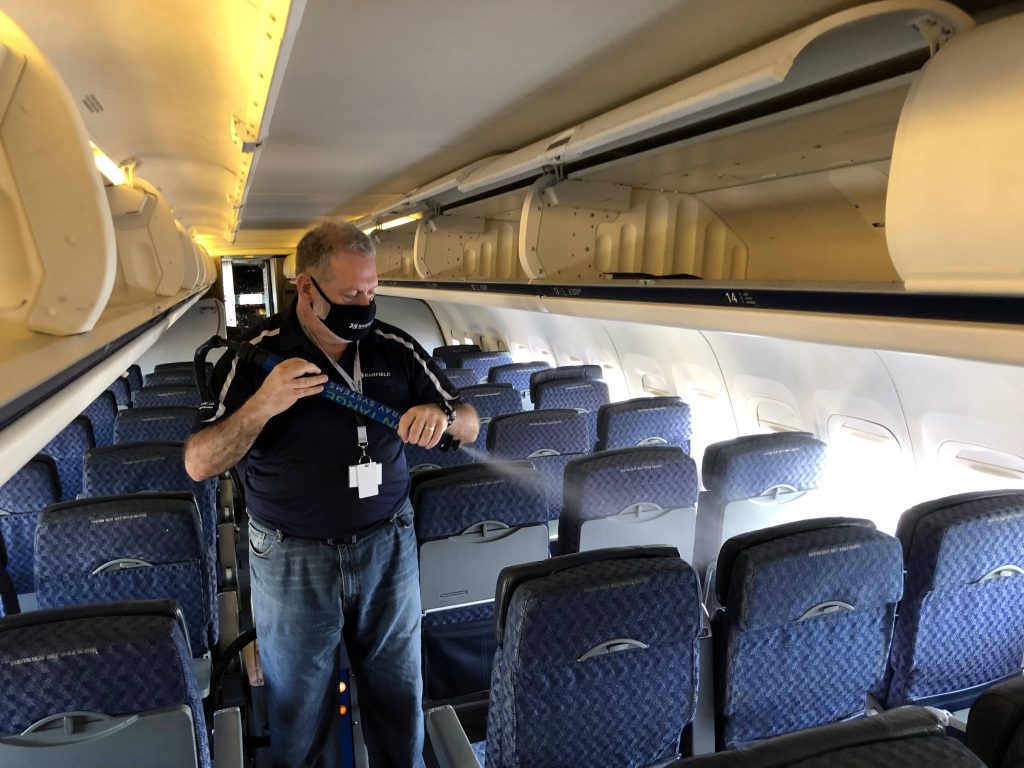
Electrostatic Sprayer On Target Barfield Aircraft 2

The Electrostatic Sprayer Cart is suitable for large areas, disinfecting in a very short period of time. It also uses less product, in comparison to a non-electrostatic unit.

Distance to objects with an Electrostatic Sprayer Cart unit varies between 3 to 6 feet, at a speed of 1 foot per second. As a result, we found that doing a row inside and aircraft could take about 3-5 seconds on average, and doing all the rows in a 737 could take around 10 to 15 minutes on average.

 This video shows the work in this aircraft:

How to interface a TT1000A and TT1200A with an Aircraft?

How to interface a TT1000A and TT1200A with an Aircraft?

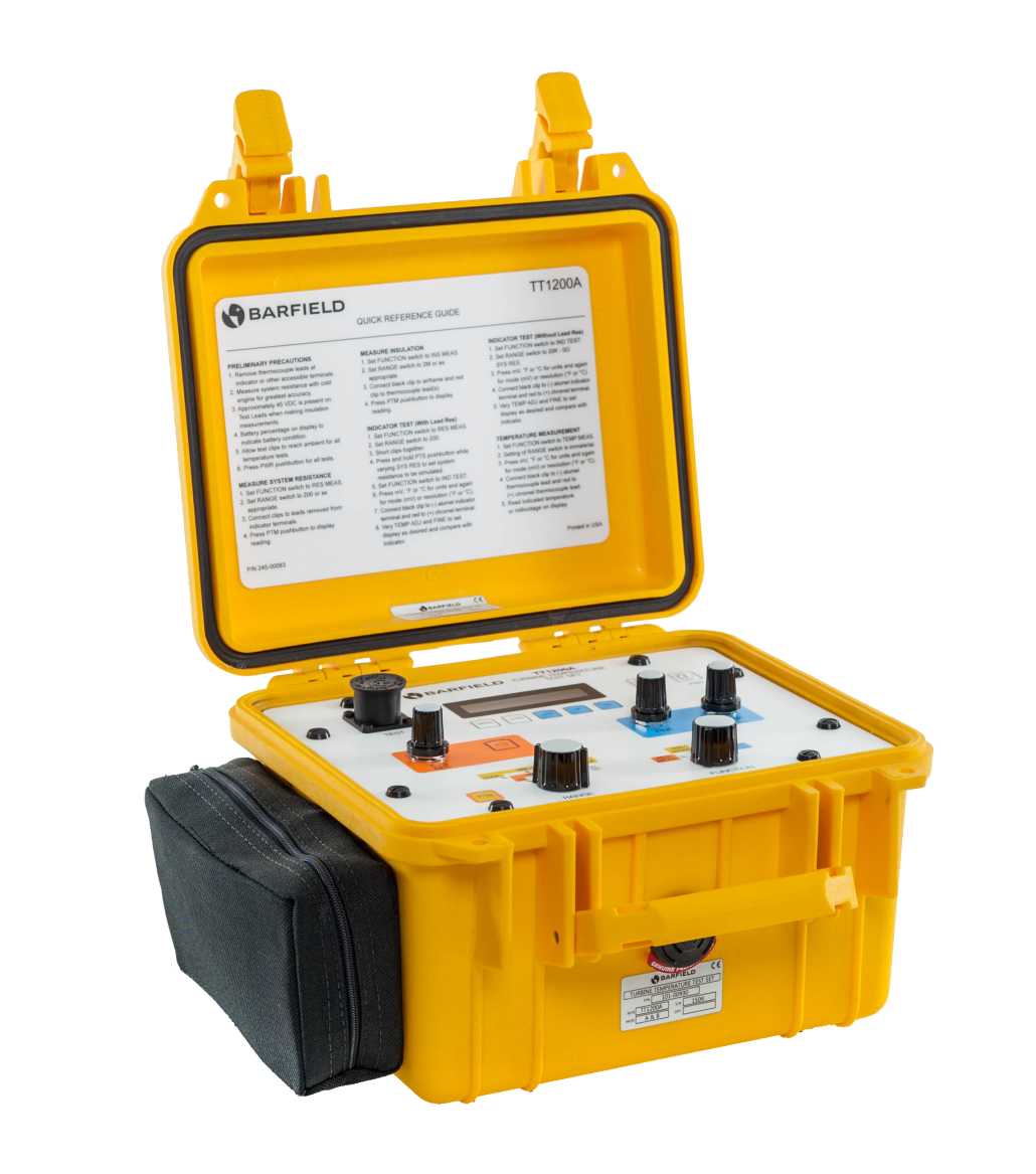
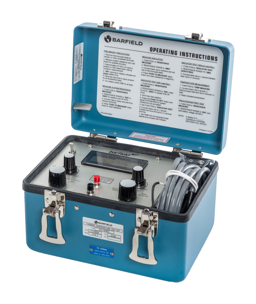
This is a brief description of some of the concerns regarding the proper point for interfacing the Barfield TT1000A and TT1200A test sets into the aircraft Turbine Temperature Indicating System. 

Where to break into the aircraft engine temperature indicating system to perform Indicator tests?   

Break at the engine terminal block

If the aircraft indicator is a servo, digital, or glass, it is recommended breaking into the system at the engine terminal block.

Test at the indicator

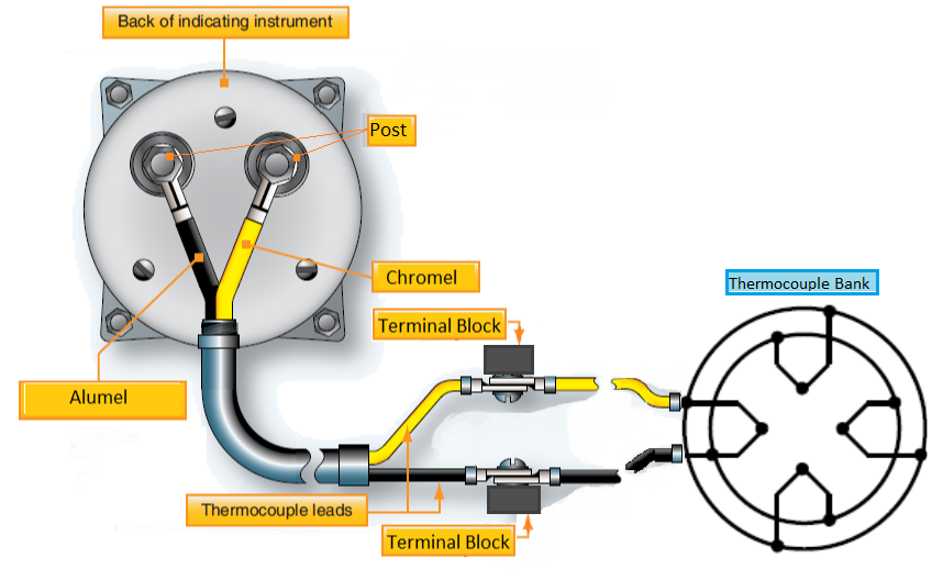
Note that if the indicator does not use aircraft power and has only 2 posts for the electrical connections then it is NOT recommended to break into the terminal block.

This type of system is powered solely by the millivoltage from the thermocouples and must be tested at the indicator.

The indicator is calibrated to measure K type thermocouple millivoltage with a specific in-line resistance, typically 8.00 ohms.

If the Test Set is configured to simulate the 8.00 ohms and interfaced at the terminal block, then the indicator will see the simulated 8 ohms plus the combined resistance of the Chromel and Alumel wire lengths between the terminal block and the indicator.

The result will be that the indicator will read lower than the Test Set display.

TT1000 Schematic Barfield

Where to find the manuals?

To learn more about the proper usage and interfacing of the test sets, please refer to the appropriate Instruction Manuals, availble on our website barfieldinc.com:  56-101-00901  or 56-101-00930  

TT1000 Temperature Tester - Barfield
TT100A
How the Frequency Domain Reflectometer  with Boeing App Works?

How the Frequency Domain Reflectometer with Boeing App Works?

 Barfield Inc., in partnership with Bird, has developed the FlightHawk ( formerly known as SiteHawk-AV), a Frequency Domain Reflectometer (FDR), designed for aviation. It is aim at reducing aircraft downtime when troubleshooting any RF cable and antenna in an aircraft. The new Boeing App creates a layer of support simplifying testing of any navigation unit.

The FLightHawk connects from the end of the coaxial cable, testing if damages exist by identify the Distance to Fault (DTF) and capable of performing a frequency sweep to the antenna.

The latest App, allows for any technician to quickly diagnose problems with the navigation system by splitting the problem with certainty between the LRU and the connection to the antenna.

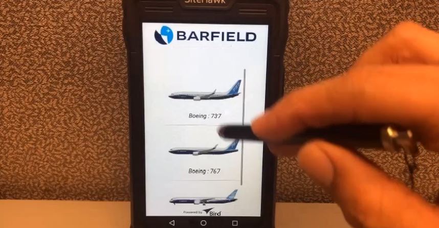
This video shows how the Automatic App made for Boeing works. Currently it is available with Boeing 737,767 and 787 coax and antenna configurations. 

The Automatic App allows to:  

  • Select an aircraft model.
  • Select the RF system.
  • It will automatically calibrate, select the cable type and the distance to the antenna for that specific system in that specific aircraft.
  • It will give you  a PASS or FAIL
  • If FAIL it will take you to the Manual mode to do the VSWR ( Voltage Standing Wave Ratio ) and DTF (Distance to Fault) analysis.

The simplicity of the App allows for any technician with some experience in avionics to run a test of any navigation unit. Qualifying the event facilitates the job for technical support, as many times expert avionics technician are not available right onsite. 

After running the test, the unit is capable of sending the information to an avionics manager, located remotely and transfer a picture of the signal via Bluetooth to a phone.  More Boeing configurations will follow.